Nylon 12 Composite – Carbon and Hollow Glass Sphere Fille

Carbon-Reinforced Lightweight Nylon PA12

Selective Laser Sintering [SLS]

Material Info

About

PA 640-GSL is a composite Nylon 12 powder optimized for selective laser sintering (SLS). Filled with both carbon fiber and hollow glass microspheres, it offers an excellent balance between strength, stiffness, weight reduction, and surface finish. With strong Z-direction performance and a dark gray finish, it is a reliable material for demanding engineering applications where stability and weight optimization are critical.

Color & Finishes

Dark Grey
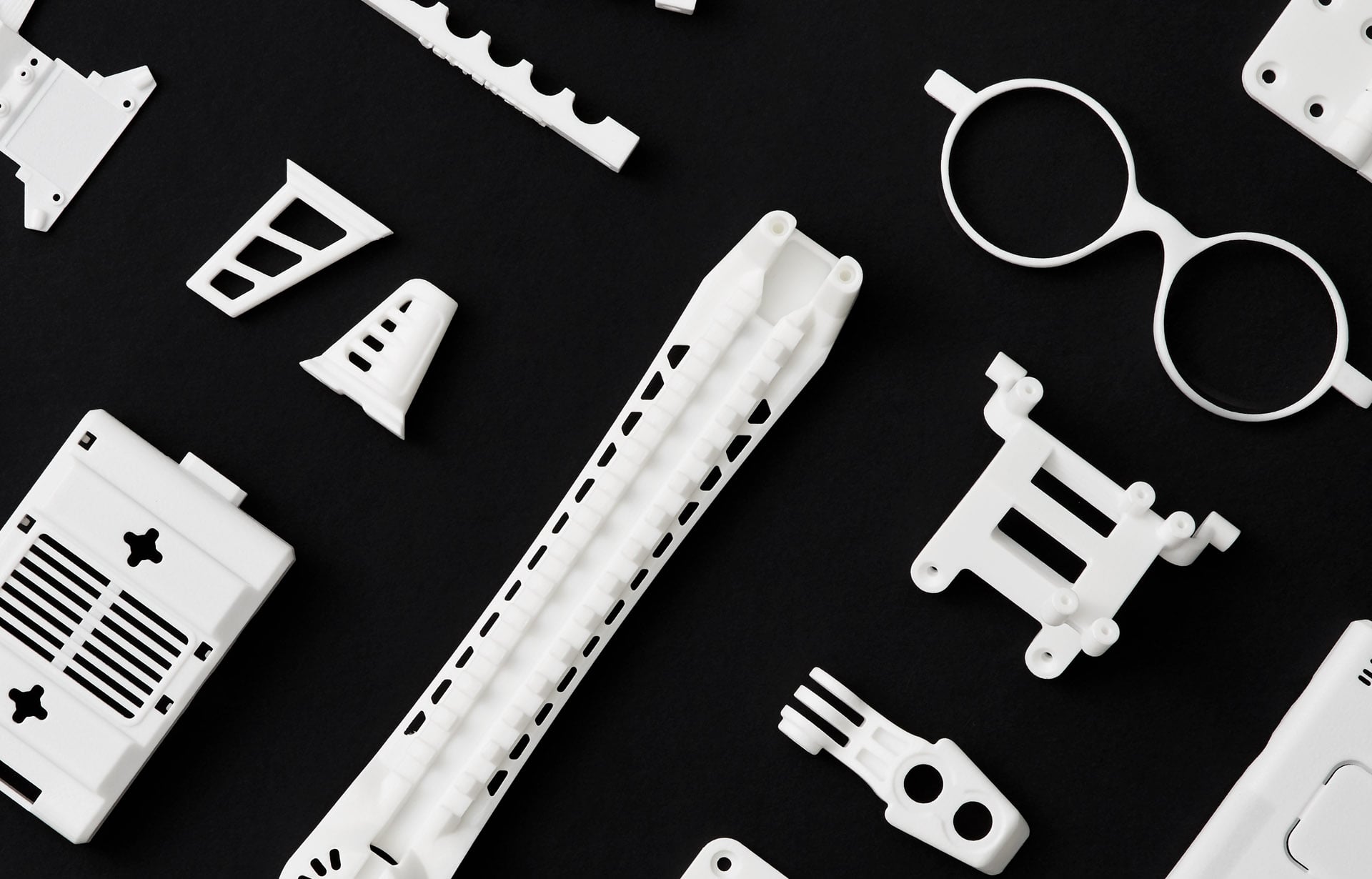
A matte finish with a fine, slightly grainy feel.
Natural
This finish has a matte finish and slightly grainy feel.
Smooth
This finish has a smooth surface and slight shine, created using a physio-chemical process to vapor smooth the surface.

Technology

  • Selective Laser Sintering [SLS]

Material Properties

Sintered Density
0.82 g/cm³
Tensile strength (ASTM D638)
49 MPa (XY) , 33 MPa (Z)
Tensile modulus (ASTM D638)
3816 MPa (XY) , 1945 MPa (Z)
Flexural Modulus (ASTM D790)
5040 MPa (XY) , 4313 MPa (Z)
Elongation at break (ASTM D638)
3%

Description

Material Highlights
Lightweight, stiff, ESD-safe, excellent strength-to-weight ratio
Electrical Properties
Electrostatic discharge (ESD) compliant
Flammability
HB rating (pass) @ 3.24 mm thickness
Applications
Lightweight structural housings, drone chassis, ESD enclosures, aerospace brackets, robotics frames

Design Guidelines

Bounding Box

Maximum Bounding Box
200 x 250 x 330 mm

Minimum Bounding Box
4 × 4 × 1 mm or X + Y + Z > 9 mm

The bounding box is a 3D imaginary outline of a box that encloses the smallest area occupied by your model. Your model must be within the minimum and maximum bounding box sizes. If the size of the model is close to the maximum bounding box, then the printing orientation will be restricted.

Walls

Supported Walls
1.5 mm
 
Unsupported Walls
1.5 mm

A supported wall is connected at least on two sides of the wall, while an unsupported wall is connected only on one side of the wall. Walls that do not meet the minimum requirements may not survive printing and cleaning processes. Additionally, models may still be rejected based on the wall geometry of the model. Please consider the size of your model and reinforce the walls or add support structures as needed as minimum guidelines will not always be adequate for large models.

Wires

Supported Wires

1.5 mm

Unsupported Wires

1.5 mm

A wire is a circular, rectangular or even triangular feature that is thinner in its unconnected directions than its length. A supported wire is connected at least on two sides of the model, while an unsupported wire is connected on one side of the model. Wires that do not meet the minimum requirements may not survive printing and cleaning processes. Additionally, models may still be rejected based on the wire geometry of the model. Please consider the size of your model and reinforce the wires or add support structures as needed as minimum guidelines will not always be adequate for large models.

Details

Embossed Details

0.7 mm

Engraved Details

0.7 mm

For text, the ratio between width and depth, should be 1:1 and sans-serif fonts are preferred for line weight consistency.

Escape Holes

Single Escape Hole Diameter

4.0mm

Multiple Escape Hole Diameter

2.0mm

Escape holes are necessary to empty the support material of a hollow model. Two escape holes at the opposite ends of the model is optimal for the support removal process. Please consider the size of your model and make the escape holes bigger or add more escape holes as needed as minimum guidelines will not always be adequate for large models.

A single escape hole at the end of a cavity will not allow material in the corners near the escape hole to fully escape. So we recommend multiple escape holes at both ends of the cavity.

Clearance

Minimum

0.6 mm

Clearance is the space between two individual parts in a model. If the space among the individual parts do not meet the minimum clearance, then parts can fuse together or can be difficult to clean. This is important for movable pieces like hinges, gears, etc.

Sprues

Supported

Sprues are wires that keep two or more parts together. Parts should be connected with a minimum of two sprues each. Please consider the size of your sprues and increase them as needed as minimum guidelines will not always be adequate for large models. If the sprues are within the guidelines and are broken, but there is no damage to your model, we will still ship them as is.

Interlocking & Enclosed Parts

Interlocking
Supported

Enclosed
Supported

Parts in File


1

Accuracy


±0.4 mm or 0.4% (standard), ±0.15 mm or 0.2% (technical tolerance)

For example, a product with dimensions of 50 × 50 × 100 mm can be 0.4 mm + 0.004 × 100 mm = 0.8 mm bigger or smaller in any direction (standard).
With technical tolerance, that becomes 0.15 mm + 0.002 × 100 mm = 0.35 mm

Related Materials

Strong and Flexible, Nylon 12 Plastic, PA12, Polyamide, PA 2200
Nylon 12 [PA12]
Application: high strength & stiffness applications, skin contact applications, thin features and interlocking parts
Learn More →
Also known as SLS PA11, Nylon 11, EOS PA11, Nylon Polyamide 11
Nylon 11 [PA11]
Application: External medical devices, automotive, sports equipment, loaded functional prototypes, hinges
Learn More →

Stay up to date on promotions, case studies, and more.

Contact Sales

"*" indicates required fields

Name*
Hidden
Hidden
Hidden
Hidden
Marketing Email Opt In*
Hidden
Hidden
Hidden
Hidden
Hidden
Hidden
Hidden
Hidden