Strong and flexible, Nylon 11 (Selective Absorption Fusion), PA11, Polyamide 11

Nylon 11 [PA11]

Multi Jet Fusion [MJF]

Material Info

About

Selective Absorption Fusion (SAF) PA11 is a high-performance, bio-based nylon powder ideal for production-grade 3D printed parts. Derived from renewable castor oil, SAF PA11 delivers outstanding ductility, high impact resistance, and excellent chemical resistance. This material is optimized for demanding applications in automotive, industrial, medical, and consumer sectors, making it a sustainable choice for strong, flexible end-use components.
More information about this printing technology can be found Here

Color & Finishes

Gray
A shade of gray that can vary in lightness
Black
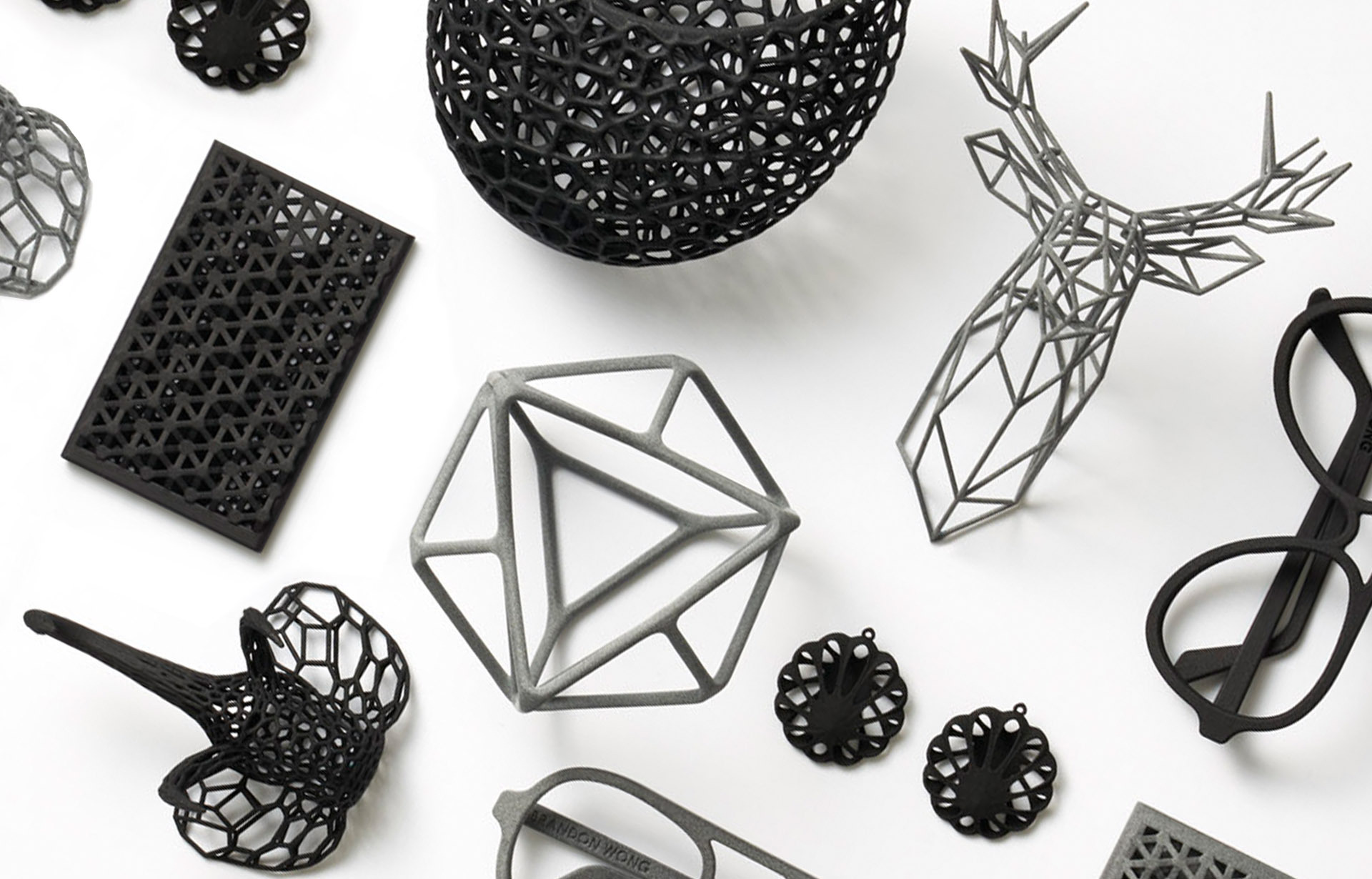
A deep matte black finish, resulting from professional dyeing.
Natural
A matte finish and slightly grainy feel.

Technology

  • Multi Jet Fusion [MJF]

Material Properties

Tensile modulus (ASTM D638)
1529 MPa (XY), 1609 MPa (Z)
Tensile strength (ASTM D638)
51 MPa (XY), 47 MPa (Z)
Elongation at break (ASTM D638)
30% (XY), 11% (Z)
Flexural modulus (23°C)(ASTM D790)
1340 MPa (XY), 1390 MPa (Z)

Description

Material Highlights
High ductility & impact resistance, good chemical resistance, professional matte finish, bio-based, thin features & interlocking parts
Flammability degree (UL 94)
HB rating (pass) at 1.6–4.2 mm thickness
Heat Deflection Temp (0.45MPa)
185°C
Biocompatibility
Non-cytotoxic, non-irritant, non-sensitizer
Applications
Durable functional parts, automotive clips, flexible hinges, industrial housings, consumer products

Design Guidelines

Bounding Box

Maximum Bounding Box
315 × 208 × 293 mm

Minimum Bounding Box
4 x 4 x 2 mm or X + Y + Z > 10 mm

The bounding box is a 3D imaginary outline of a box that encloses the smallest area occupied by your model. Your model must be within the minimum and maximum bounding box sizes. If the size of the model is close to the maximum bounding box, then the printing orientation will be restricted.

Walls

Supported Walls
0.5 mm
 
Unsupported Walls
0.7 mm

A supported wall is connected at least on two sides of the wall, while an unsupported wall is connected only on one side of the wall. Walls that do not meet the minimum requirements may not survive printing and cleaning processes. Additionally, models may still be rejected based on the wall geometry of the model. Please consider the size of your model and reinforce the walls or add support structures as needed as minimum guidelines will not always be adequate for large models.

Wires

Supported Wires

0.7 mm

Unsupported Wires

1.0 mm

A wire is a circular, rectangular or even triangular feature that is thinner in its unconnected directions than its length. A supported wire is connected at least on two sides of the model, while an unsupported wire is connected on one side of the model. Wires that do not meet the minimum requirements may not survive printing and cleaning processes. Additionally, models may still be rejected based on the wire geometry of the model. Please consider the size of your model and reinforce the wires or add support structures as needed as minimum guidelines will not always be adequate for large models.

Details

Embossed Details

0.5 mm

Engraved Details

0.5 mm

For text, the ratio between width and depth, should be 1:1 and sans-serif fonts are preferred for line weight consistency.

Escape Holes

Single Escape Hole Diameter

4.0 mm

Multiple Escape Hole Diameter

2.0 mm

Escape holes are necessary to empty the support material of a hollow model. Two escape holes at the opposite ends of the model is optimal for the support removal process. Please consider the size of your model and make the escape holes bigger or add more escape holes as needed as minimum guidelines will not always be adequate for large models.

A single escape hole at the end of a cavity will not allow material in the corners near the escape hole to fully escape. So we recommend multiple escape holes at both ends of the cavity.

Clearance

Minimum

0.5 mm

Clearance is the space between two individual parts in a model. If the space among the individual parts do not meet the minimum clearance, then parts can fuse together or can be difficult to clean. This is important for movable pieces like hinges, gears, etc.

Sprues

Supported

Sprues are wires that keep two or more parts together. Parts should be connected with a minimum of two sprues each. Please consider the size of your sprues and increase them as needed as minimum guidelines will not always be adequate for large models. If the sprues are within the guidelines and are broken, but there is no damage to your model, we will still ship them as is.

Interlocking & Enclosed Parts

Interlocking
Supported

Enclosed
Supported

Parts in File


1

Accuracy


± 0.30 mm, or ± 0.3 % of the longest axis (whichever is larger).

For example: a product designed at 50 × 50 × 100 mm will be produced within –0.30 mm to +0.30 mm of its nominal size in every direction.

Related Materials

Also known as HP Multi Jet Fusion PA12, Professional Plastic, HP Nylon Plastic, PA12, Polyamide
Nylon12 - [PA12]
Application: Mechanical & structural parts, mounts, cases, eye frames, tech accessories, drone parts, home decor, miniatures, art, prosthetics
Learn More →
Also known as HP PA12 Glass Beads, PA12 GB, Glass-filled PA12, PA12 GF, Nylon 12 GB
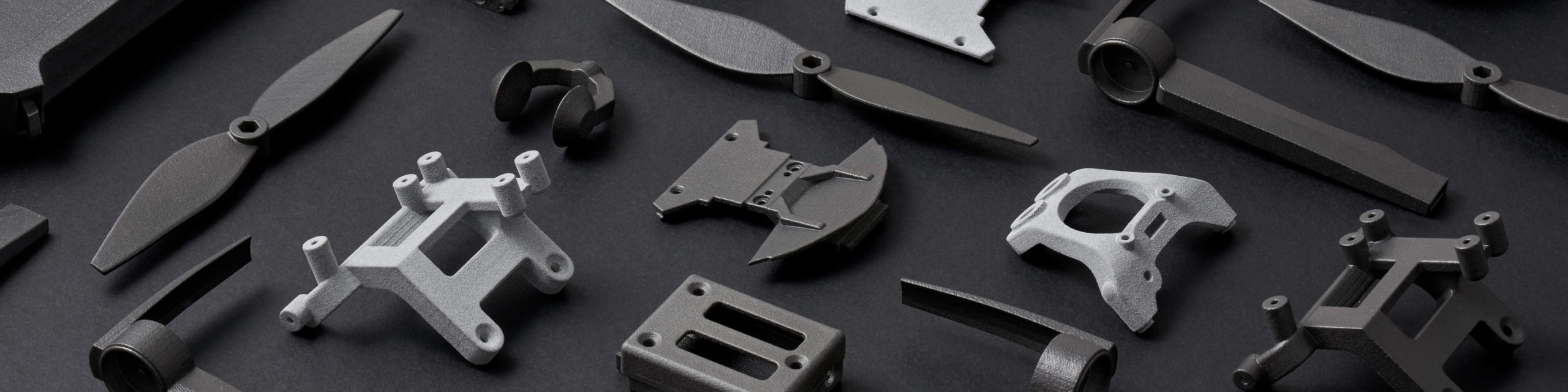
Nylon 12 Glass Beads [PA12 GB]
Application: Tooling, Robotics, Drones, Fixtures, Medical Braces, Housings, Cases
Learn More →

Stay up to date on promotions, case studies, and more.

Contact Sales

"*" indicates required fields

Name*
Hidden
Hidden
Hidden
Hidden
Marketing Email Opt In*
Hidden
Hidden
Hidden
Hidden
Hidden
Hidden
Hidden
Hidden