Natural Bronze


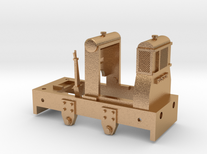
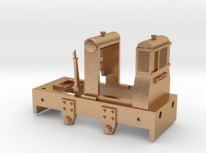
Small Ruston Hornsby Loco Body Part 1a
Made by
Print With Shapeways
 Choose Your Material
 Choose your color and finish
$42.12
Have a question about this product?
contact the designerYou must be logged in and verified to contact the designer.
Product Description
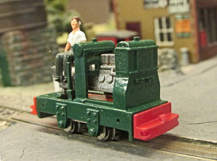
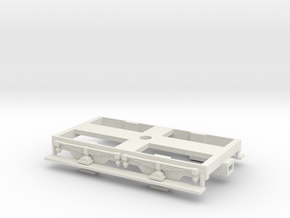
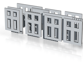
Small Ruston Hornsby 0-4-0 Diesel Locomotive
Scale: 009 (4mm/fit scale 9mm gauge Track).
Ruston & Hornsby, later known as Ruston, was an industrial equipment manufacturer in Lincoln, England. They were probably best known for their narrow and standard gauge diesel locomotives and excavators.
These small locomotives were supplied to various locations throughout the United Kingdom, the British Empire and the rest of the world. These included water treatment works, gravel pits, slate and other quarries, also various industrial sites and lightly laid agricultural lines.
Many have since found their way onto Miniture and Heritage Railways.
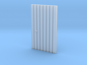
This Print contains Part 1a only (the main body casting) and is based on earlier production models. This is best printed in either Natural Brass or Bronze to add weight. However, I have also made it available in Fine Detailed plastic for static models.
Note: Other components will be needed to compleat the model
ASSEMBLY INSTRUCTIONS
Sub-assembly 1
1. Mainframe (Parts 1a) and Buffer (Part 2 available separately).
If the body colour is to be a different colour than that of the buffers it is recommended that the buffers are painted while still on the sprue.
(i) Leaving the buffers still attached, cut the sprue roughly in half;
(ii) Thread one buffer sprue through the appropriate hole in the end of the mainframe, ensuring that the coupling lug is uppermost and secure with cyanoacrylate glue;
(iii) Once set, cut the sprue off flush to the inside the body;
(iv) Repeat steps (ii) and (iii) for the other end.
Sub-assembly 2
2. Internal Detail (Parts 3a or 3b and 4 all available separately).
Note: Part 4 is contained within the same print as Part 2.
There are two alternative engine units. Part 3a with a long exhaust pipe which comes out on the locos left side just above the frames, while Part 3b has a ‘mushroom’ shaped exhaust on the left side of the cylinder block. The latter is intended for use on locos without the optional bonnet but those with the long exhaust could sometimes be seen without bonnets as well.
It is recommended that both these parts are painted first since access will be difficult later.
(v) Slide the engine mounting (part 4) over the two prongs at the front of the engine unit (part 3a or 3b) with the narrow, stepped end at the bottom and the small chamfer along the top edge facing away from the cylinder block.
(vi) Push the engine mounting right up against the cylinder block but do not glue.
(vii) Thread this sub-assembly through the hole in the cab floor of Subassembly 1 from the underside and swing the front upwards until almost level and pull forward until the two prongs at the front of the engine unit touch the back of the radiator.
The back of the engine unit should now rest on the cab floor in the ‘U’ shaped locator.
(viii) Push the engine mounting right up against the back of the radiator to lock the engine unit in place.
(ix) Any slop should be taken up by ensuring the back of the engine unit is hard against the ‘U’ shaped locator. At this point it may be necessary to apply a small drop of cyanoacrylate glue along the top of the engine mounting block to secure the assembly.
(x) To represent the gear change lever, glue a length of 1mm brass rod into the square hole to the right (as the driver would sit) of the seat. When the glue has set, cut off the wire so that a length of approximately 8mm projects above the hole.
A suitable chassis may now be fitted.
Scale: 009 (4mm/fit scale 9mm gauge Track).
Ruston & Hornsby, later known as Ruston, was an industrial equipment manufacturer in Lincoln, England. They were probably best known for their narrow and standard gauge diesel locomotives and excavators.
These small locomotives were supplied to various locations throughout the United Kingdom, the British Empire and the rest of the world. These included water treatment works, gravel pits, slate and other quarries, also various industrial sites and lightly laid agricultural lines.
Many have since found their way onto Miniture and Heritage Railways.
This Print contains Part 1a only (the main body casting) and is based on earlier production models. This is best printed in either Natural Brass or Bronze to add weight. However, I have also made it available in Fine Detailed plastic for static models.
Note: Other components will be needed to compleat the model
ASSEMBLY INSTRUCTIONS
Sub-assembly 1
1. Mainframe (Parts 1a) and Buffer (Part 2 available separately).
If the body colour is to be a different colour than that of the buffers it is recommended that the buffers are painted while still on the sprue.
(i) Leaving the buffers still attached, cut the sprue roughly in half;
(ii) Thread one buffer sprue through the appropriate hole in the end of the mainframe, ensuring that the coupling lug is uppermost and secure with cyanoacrylate glue;
(iii) Once set, cut the sprue off flush to the inside the body;
(iv) Repeat steps (ii) and (iii) for the other end.
Sub-assembly 2
2. Internal Detail (Parts 3a or 3b and 4 all available separately).
Note: Part 4 is contained within the same print as Part 2.
There are two alternative engine units. Part 3a with a long exhaust pipe which comes out on the locos left side just above the frames, while Part 3b has a ‘mushroom’ shaped exhaust on the left side of the cylinder block. The latter is intended for use on locos without the optional bonnet but those with the long exhaust could sometimes be seen without bonnets as well.
It is recommended that both these parts are painted first since access will be difficult later.
(v) Slide the engine mounting (part 4) over the two prongs at the front of the engine unit (part 3a or 3b) with the narrow, stepped end at the bottom and the small chamfer along the top edge facing away from the cylinder block.
(vi) Push the engine mounting right up against the cylinder block but do not glue.
(vii) Thread this sub-assembly through the hole in the cab floor of Subassembly 1 from the underside and swing the front upwards until almost level and pull forward until the two prongs at the front of the engine unit touch the back of the radiator.
The back of the engine unit should now rest on the cab floor in the ‘U’ shaped locator.
(viii) Push the engine mounting right up against the back of the radiator to lock the engine unit in place.
(ix) Any slop should be taken up by ensuring the back of the engine unit is hard against the ‘U’ shaped locator. At this point it may be necessary to apply a small drop of cyanoacrylate glue along the top of the engine mounting block to secure the assembly.
(x) To represent the gear change lever, glue a length of 1mm brass rod into the square hole to the right (as the driver would sit) of the seat. When the glue has set, cut off the wire so that a length of approximately 8mm projects above the hole.
A suitable chassis may now be fitted.
Details
What's in the box:
RH Small Part 1a
Dimensions:
Success Rate:
First To try.
What's this?
Rating:
Mature audiences only.

More From This Shop
$7.50
$57.39